2016年12月21日星期三

Basic of Line Scan System

With the large-scale popularization of machine vision and the improvement of industrial assembly line speed and the accuracy, the line scanning system is increasingly being recognized by visual engineers and end users.

Line Scan System
A line scanning system is usually used on the occasion that there is relative motion between the measured object and the camera. The image is acquired line by line through line scan cameras. The maximum line rate of line scan cameras usually is very high. For example, Contrastech’s Mars2048-50LGM could operate at a maximum line rate of 50 kHz, or at a maximum of 50,000 lines per second.


The difference of the image acquired by line scan cameras and area scan cameras is that the length of the image acquired by line scan cameras could be infinitely long. Then, the software will cut this "infinitely long" image into certain height images to do real-time processing or put it into the buffer for later processing. ContrasTech’s line scan cameras all support 256MB onboard buffer, for data transmission and image reload under burst mode.
line scanning
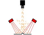
Generally, a line scanning system includes vision part and motion control part. The vision part contains line scan cameras, lens, light source, image grabber and vision software. The motion control part includes motor, motor driver, motion control card or PLC, and sometimes also need an encoder in order to ensure the synchronization between the collection of images and conveyor belt.

Due to a large amount of line scan information, it will need a high performance of the industrial computer with large capacity memory and the hard disk; also its motherboard should provide PCI, PCI-E or PCI-X slot.

Generally, the way to choose an area scanning system is usually in this order: Camera→Lens→Light source. It is similar to line scan system. First, determine the resolution and line scan speed of the camera by requirements of the speed and the size of the detail to be inspected. Then choose a right lens with right interface. Last, choose a right light source.

Selection of line scan cameras
A system scanning a 1600mm wide object which requires a pixel with a horizontal distance of 1mm. This would be the smallest feature size of the object. In order to calculate the required camera resolution for this application, you take the field of view and divide by the smallest feature size (which in this case is 1mm). The resulting calculation would be 1600/1= 1600 pixels. Therefore, this application would need a camera with a resolution of at least 1600 pixels.
line scan cameras
Cameras are available with a variety of fixed sensor resolutions (none of which are 1600) so the best choice would be a camera with 2048 pixels. The 1600mm field of view will be applied across the 1600 pixels of the array and a minimum feature size of 1mm will be maintained. Since the camera has an array of 2048 pixels there will be pixels on either side of the image which will extend beyond the field of view. So if you get the pixels fully used, the actual minimum feature size of the object will be changed. The resulting calculation would be 1600/2048=0.8mm.

Camera speed also needs to be considered. A standard ContrasTech’s Mars2048-50LGM camera will operate at a maximum line rate of 50 kHz, or at a maximum of 50,000 lines per second. If you were to use this camera with this case application, where one line represents 1mm, the system could run at a maximum object speed of 22000mm per second. The minimum line rate of the camera would be 22000/0.8mm=27.5KHz so Mars2048-50LGM could fit the requirements.

Selection of lens for line scan cameras
The common resolutions of line scan cameras are 1K, 2K, 4K, 6K, 8K, 12K; and the pixel sizes are 5μm, 7μm, 10μm, 14μm. Therefore the sensor size could be from 10.240mm (1K*10μm) to 86.016mm (12K*7μm). Obviously, C-Mount can not meet the requirements, because the largest compatible sensor size for C-Mount can only up to 22 mm, which is 1.3inch. And many line scan camera’s mounts are F-Mount, M42*1, M72*0.75. Different lens mounts have different Flange distance, which also determines the different working distance.

Magnification(β): After the resolution and pixels of the camera are determined, then you could know the sensor. ContrasTech’s Mars2048-50LGM have a resolution of 2048pixels and 10μm pixel size. The resulting calculation of the sensor size is 2048*10μm=20.48mm. Therefore, the Magnification could be calculated by this simple formula: β= sensor size/FOV.

Flange Distance: It means the distance from the camera mount plane to the sensor. It’s quite an important parameter, which is determined by each manufacturer according to their own optical design. Cameras from different manufacturers have different flange distances, even they have the same lens mount.

With magnification, lens mount and flange back, then the working distance and the length of the extension tubes could be determined.


Contact Hangzhou ContrasTech Co., Ltd Add.: No.11, Xiyuan 8th Road West Lake District, Hangzhou 310030 China TEL: 86-571-89712238 Fax: 400-8266-163*01460 Website: www.contrastech.com E-mail: sales6@contrastech.com

2016年12月9日星期五

Different Types of Machine Vision Illumination

Bright Field:
Light is aimed directly at an object, often creating distinct shadows.  This type of lighting is effective when used on objects requiring high degrees of contrast, but creates specular reflections when used with shiny or reflective materials.
 

Dark Field:
Light is projected at an angle to the surface, causing any variations to deflect light up into the camera, creating bright spots on a dark background or field.  Nothing is seen by the vision system if there are no aberrations on the surface.

Back Lighting:
An even field of illumination is projected from behind an object, which is seen as a silhouette by the camera.  Backlighting is most commonly used for taking measurements or determining part orientation.
 
Diffuse Light: Reflected light, providing a non-directional, soft illumination free of harsh shadows that is well suited for highly specular objects.  This illumination effect is similar to the type of light found on an overcast day.
 
Co-Axial Illumination:
A variation of diffuse light in which light is aimed at an angled beam splitter that reflects the light down.  The object is viewed from above through the beam splitter.  This light type is particularly helpful on highly reflective objects or in situations where the area of inspection is obscured by shadows from its surroundings. 
 

Each light type has a specific purpose, but is also adaptable for a range of applications not immediately related to its function. For example, a spotlight, which provides bright field illumination, can be placed at an angle to create a dark field effect.  For some applications, the best results are achieved by combining multiple light types.

2016年10月19日星期三

Types of Machine Vision Illumination Sources

Types of Machine Vision Illumination Sources


Generally, machine vision has three technical advantages: Acquisition Technology, Processing Technology, and Motion Control Technology. Choosing different machine vision light source is in order to acquire high contrast and high quality images. It is very importanrt to choose a high quality and appropriate light source for creating a robust and timely vision inspection.

Types of illumination
The following lighting sources are now commonly used in machine vision:

1. Fluorescent light (high frequency)
2. Quartz Halogen incandescent lamps – Fiber Optics
3. LED - Light Emitting Diode
4. Metal halide light sources (as "cold light" sources with fibre optic transmission)
5. Xenon strobe lamps and metal halide lamps are used quite rarely in industrial machine vision
 

Fluorescent, quartz-halogen, and LED are by far the most widely used lighting types in machine vision, particularly for small to medium scale inspection stations, whereas metal halide and xenon are more typically used in large scale applications, or in areas requiring a very bright source. Metal halide, also known as mercury, is often used in microscopy because it has many discrete wavelength peaks, which complements the use of filters for fluorescence studies.  A xenon source is useful for applications requiring a very bright, strobed light.

The figure-1 is a comparison and contrast of common vision lighting sources which shows the dvantages and disadvantages of fluorescent, quartz halogen, and LED lighting types.

Figure-1 Comparison and contrast of common vision lighting sources 
Figure-1 Comparison and contrast of common vision lighting sources

Advantages of LED lighting
1. It’s capable to be design in almost any housing shapes for different machine vision purpose.
2. Its light colour is not only white, but also red, green or blue, infrared or even ultraviolet. And the light intensity could be adjusted by light control units.
3. It has a long life expectancy compared to other lighting.
Type
Fluorescent light
Halogen incandescent lamps 
LED Lighting
Life expectancy
1500-3000hrs
1000hrs
30000hrs
4. Quick resopnse: it could achieve the maximum brightness in 10μs or even less.
5. It could be use as a strobe light by control units.
6. It also could be customized easily according to specific needs.

Therefore, LED lightings are widely used in many industrial machine vision applications.

ConstrasTech’s LED machine vision light source distinguishes itself by high intensity, high brightness and a long life time. And we are still devoted tocontinuously develop new products and improve its functionality. Now we already have a variety of LED machine vision lights available now.
Machine Vision Lights


Contact
Hangzhou ContrasTech Co.,Ltd

Add.: No.11, Xiyuan 8th Road West Lake District,
Hangzhou 310030 China
TEL: 86-571-89712238
Fax: 400-8266-163*01460
E-mail: market@contrastech.com/sales6@contrastech.com

Tips For Choosing Industrial Lens

Tips For Choosing Industrial Lens

From: http://www.contrastech.com/content/?897.html

The process of choosing a industrial lens is the process to confirm every parameters of the lens gradually. As a imaging device, Lenses are usually used to work with the cameras and machine vision lights to constitute a complete machine vision system. Therefore, the choice of lenses should take the whole system into consideration. Generally, the following aspects is what you may need to consider when choosing industrial lenses:

Focal Length
Generally, focal length is the easy prat to make sure when choosing a right lens. Firstly, choose varifocal lenses when it needs to change the magnification in the imaging process, otherwise use a fixed focal length.

The magnification represents the relationship between the size of the image and that of the object:
 
For example; the length of a screw is 5cm and the resulting image should be 5 mm, the magnification is therefore 0.1. If, however, the screw size is only 0.5 mm and is to be represented by an image of 5 mm, the magnification is 10.

Magnification also depends on the working distance. The more distant the object the smaller the image. Thus, the use of the parameter magnification only makes sense if we know the working distance at the same time. It seems like not so pratical for our everyday life. So there are another parameter which describes a lens more clearly.  That is the focal length.


Special Requirements
Firstly, you need to take all the special requirements of the application into consideration, if there are. For example, it requires measurement function or not; it requires telecentric lense or not; it requires a large imaging DOF or not. Commonly, the depth of field(DOF) often gets ignored, but it is the thing that every imaging system should take into consideration.

DOF&Aperture
In reality, our eyes do not register a small blurred spot as being blurred. This tolerance of our eyes is the basis for the effect called "depth of field". In the case of camera sensor, the size of the pixel can be defined as a blurred spot. For example, the pixel size of our Mars series cameras is 4.8 * 4.8μm.

The camera lens aperture, or more specifically, the size of the lens aperture opening determines the amount of light that reaches the camera's image sensor.

The various lens aperture settings are called "F Stops". The aperture settings with the lower F Stop numbers allow more light to reach the image sensor than the settings with the higher F Stop numbers. The following figure descripes the relation between the aperture and DOF.

In practice, it is rarely necessary to calculate depth of field exactly. Depth of field is often a matter of belief rather than a matter of fact. Therefore, it is worth having a closer look at depth of field formula in order to find the corelation:

 
So, we can see from the formula, DOF not only has relation with Aperture, also blur spot, working distance and focal length.

In conclusion; depth of field is reliant upon 3 parameters:
Blur spot:          The smaller the blur spot, the smaller the depth of field.
Iris:                The smaller the F-stop , the smaller the depth of field.
Working distance:  The smaller the working distance, the smaller the depth of field.
Focal length:     The larger the focal length, the smaller the depth of field. The relationship is quadratic. Thus, even a small increase of the focal length leads to a considerable decrease of the depth of field.

Image Circle&Image Quality
The image size of the selected lens should be compatible with the sensor size of the camera--Large image size with smaller sensor size, that is, the format of the lens has to be larger than or equal to the format of the CCD. Otherwise, the image quality of the edge field of view could not be guaranteed.
 
CCD Formats

The image quality mainly focus on two parameters: MTF and Distortion. In the application of measurement, the distortion should pay more attention.

C&CS Mount
The common types of lens mount found in machine vision are C-mount and CS mount. C-mount or CS-Mount lenses provide a male thread, which mates with a female thread on the camera. The CS mount version only differs from this in the so-called flange focal distance The flange focal distance is 17.526 millimetres for a C mount and 12.50 for a CS-mount.


Basicly, the above things is what you need to concern when choosing a FA lens for you imaging systems. Also there are other types of lens, such as telecentric lens, which could have a better DOF and low image distortion.

For More Information
Contact US
Hangzhou ContrasTech Co.,Ltd

Add.: No.11, Xiyuan 8th Road West Lake District,
Hangzhou 310030 China
TEL: 86-571-89712238
Fax: 400-8266-163*01460
Web site: www.contrastech.com
E-mail: market@contrastech.com/sales6@contrastech.com